PS Suspension Logging
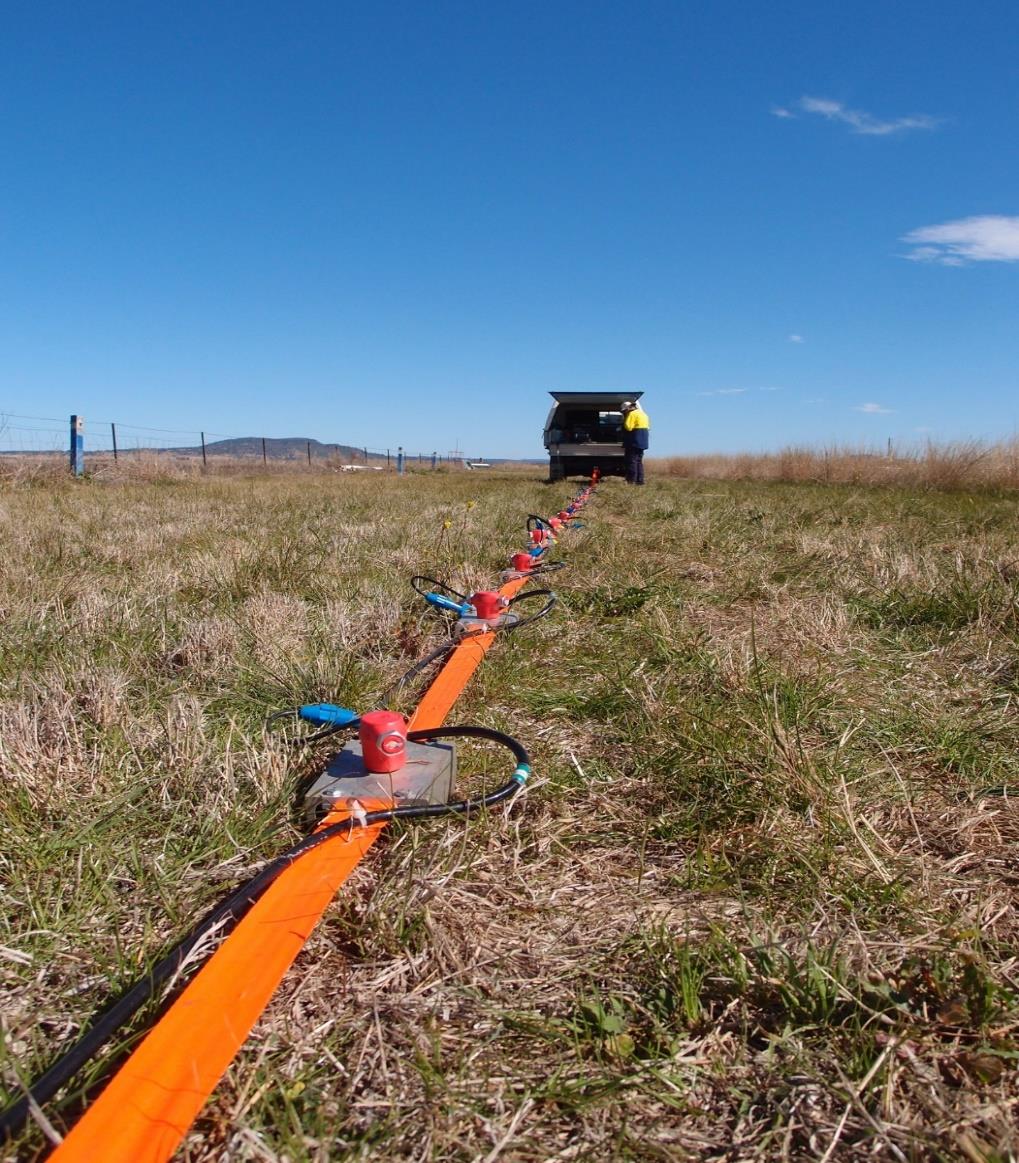
PS suspension logging measures compression (P) and shear (S) wave velocities in a borehole at close depth intervals, typically every half to one metre. A single probe about seven metres long contains a seismic source and two receivers set one metre apart, isolated by flexible filters. The probe is lowered into a fluid-filled borehole, uncased or cased with PVC, and at each depth the source generates pressure waves in the fluid that convert to P and S waves in the surrounding ground. The difference in arrival time between the two receivers gives the velocity of that interval. Because no surface source is needed, it works to depths beyond 100 metres for seismic site response and dynamic analysis.
Full-Wave Sonic Logging
Full-wave sonic logging records the complete acoustic waveform as sound travels along the borehole wall, rather than only the first arrival. A logging probe containing one or more transmitters and an array of receivers is lowered on a wireline cable into a fluid-filled borehole and logged continuously upward. Monopole sources give compression wave velocity in rock, while dipole sources can also measure shear velocity in softer formations. Stoneley and other waves in the record indicate open fractures and permeability. From the velocities and density, engineers calculate dynamic elastic properties such as Poisson's ratio and Young's modulus. The logs support rock mass characterisation, tunnel and foundation design, and correlation between boreholes.
Standard Down Hole Seismic
The downhole seismic test measures how fast P and S waves travel from the ground surface to points down a single borehole. The borehole is cased with PVC and grouted so the casing is in firm contact with the soil or rock. A triaxial geophone is lowered and clamped to the casing wall at regular intervals, often every metre. At the surface beside the borehole, a sledgehammer strikes a steel plate for P waves or the ends of a loaded wooden beam for S waves. Arrival times at each depth give interval and average velocities. The test follows procedures such as ASTM D7400 and supports seismic site classification and dynamic soil properties for design.
Standard Cross Hole Seismic
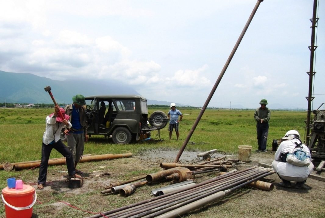
The crosshole seismic test measures P and S wave velocities horizontally between two or three boreholes drilled in a line a few metres apart. Each borehole is cased and grouted, and a deviation survey records its exact path so true distances can be calculated. A downhole source in one borehole and receivers in the others are positioned at the same depth, and travel times are recorded before both are moved to the next level. Because the waves travel through a single layer, the method gives detailed velocity profiles that can identify thin soft or stiff layers. It follows ASTM D4428 and is used for seismic design, machine foundations and critical structures.
Cross Hole Seismic Tomography
Crosshole seismic tomography builds a two-dimensional image of seismic velocity in the ground between two boreholes. A source is fired at many depths in one borehole while a string of hydrophones or geophones in the other records each shot, so that thousands of ray paths criss-cross the plane at different angles. Specialist software inverts the travel times into a velocity image of the panel between the holes. Low-velocity zones can indicate cavities, fractured or weathered rock and loose fill, while high-velocity zones show sound rock or grouted ground. The method is used to investigate karst beneath foundations, check ground improvement and grouting, and assess rock quality for tunnels and dams.
Seismic Cone Penetration Test (SCPT)
The Seismic Cone Penetration Test (SCPT) combines a standard cone penetration test with a downhole seismic measurement in one sounding. An instrumented cone with one or more geophones above the tip is pushed into the ground by a hydraulic rig at a constant rate, recording tip resistance, sleeve friction and pore water pressure continuously. Pushing pauses at set intervals, typically each metre, while a shear wave is generated at the surface by striking a steel beam pressed against the ground. The arrival time at the cone gives shear wave velocity with depth. SCPT is efficient in soft to medium soils and provides stratigraphy, strength and stiffness data for seismic and foundation design.
Other capabilities in this service
Back to Geophysical ServicesDiscuss your project with ATLAS GES
Tell us about your site and requirements, and our team will get back to you.
Get in Touch