Seismic Refraction & Reflection
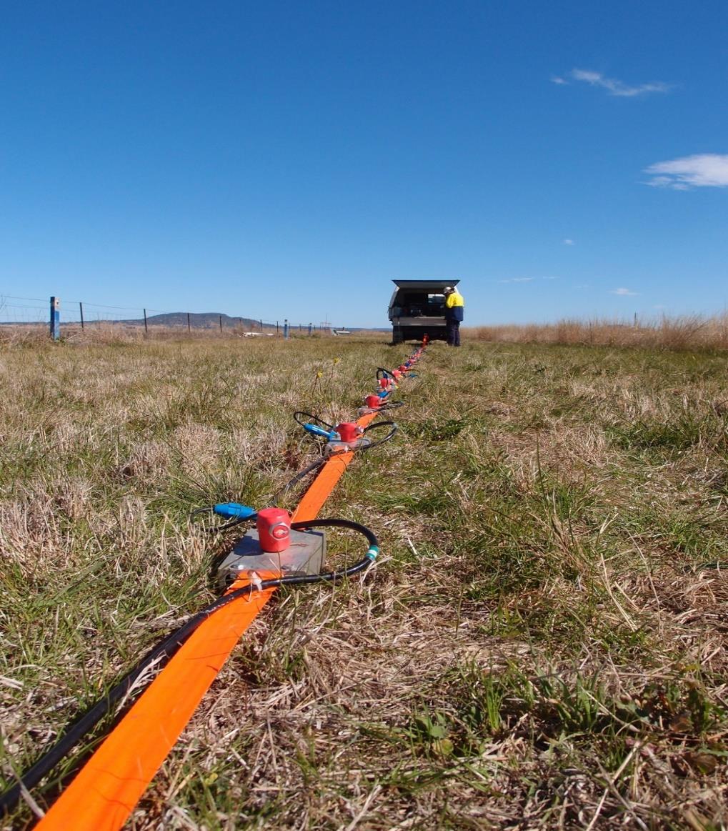
Seismic refraction and reflection surveys image the subsurface by timing how sound waves travel through the ground. A line of geophones is laid out on the surface and connected to a multichannel seismograph, and energy is generated by a sledgehammer, weight drop, small explosive charge or vibrator truck. Refraction records the first waves that bend along faster layers, giving layer velocities and the depth to bedrock or the water table. Reflection records echoes from deeper interfaces to map layering, faults and buried channels. In engineering projects the results are used to estimate rippability and excavation effort, plan foundations, locate weak zones and guide where boreholes should be drilled.
Seismic Surface Waves (MASW/SASW)
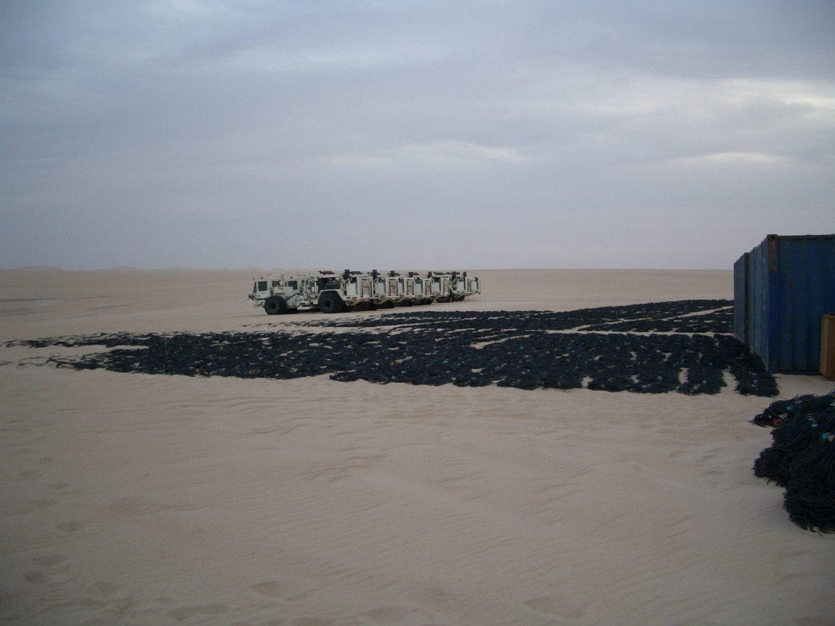
Surface wave methods measure how the speed of Rayleigh waves changes with frequency, a property called dispersion, and convert it into a profile of shear wave velocity with depth. In SASW (Spectral Analysis of Surface Waves) a pair of receivers is used and the spacing is changed between shots. In MASW (Multichannel Analysis of Surface Waves) a line of typically 24 to 48 low-frequency geophones records a hammer or weight-drop source in one setup, which is faster and more robust. Passive versions use ambient noise to reach greater depths. Shear wave velocity is a direct measure of soil and rock stiffness, so the results support seismic site classification, foundation design, compaction checks and ground improvement verification.
Electrical Resistivity Tomography (ERT)
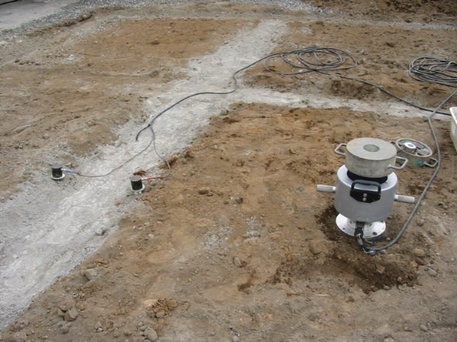
Electrical Resistivity Tomography (ERT) maps how strongly the ground resists the flow of electric current. Dozens of steel electrodes are hammered into the ground at equal spacing along a line and connected by a multicore cable to an automated resistivity meter. The instrument injects current through one pair of electrodes and measures the voltage across other pairs, cycling through hundreds or thousands of combinations. Software then inverts the readings into a two- or three-dimensional cross-section of true resistivity. Because clay, saline water, dry sand, voids and solid rock have very different resistivities, ERT is used to map depth to bedrock, detect karst cavities, locate groundwater and saline intrusion, and support earthing design.
Vertical Electrical Sounding
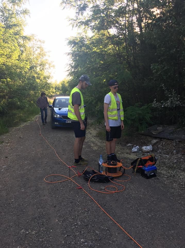
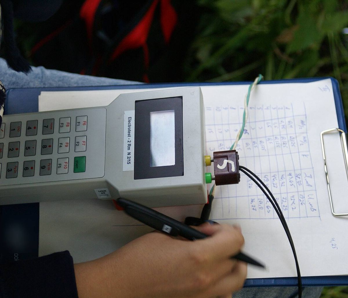
Vertical Electrical Sounding (VES) is a one-dimensional resistivity method that shows how the electrical properties of the ground change with depth at a single point. Four electrodes are placed in a straight line, usually in a Schlumberger or Wenner arrangement, and a resistivity meter passes current through the outer pair while measuring voltage across the inner pair. The outer electrodes are moved progressively farther apart, so the current penetrates deeper with each reading. The resulting curve of apparent resistivity against spacing is interpreted as a sequence of layers with thickness and resistivity. VES is used for groundwater exploration, estimating depth to bedrock and measuring soil resistivity for electrical grounding systems.
Ground Penetrating Radar (GPR)
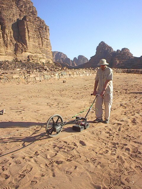
Ground Penetrating Radar (GPR) sends short pulses of high-frequency radio energy into the ground or a structure and records the reflections that return from changes in material. The antenna is mounted on a cart, sled or handheld unit and moved along survey lines, producing a continuous image called a radargram in real time. Low-frequency antennas see deeper, while high-frequency antennas give finer detail near the surface. GPR is used to locate buried utilities, pipes and tanks, map voids and shallow cavities, measure pavement and layer thickness, and scan concrete for reinforcement. Penetration is limited in clay-rich or saline ground, so site conditions are assessed before the method is chosen.
Vibration Monitoring
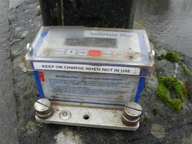
Vibration monitoring measures ground and structural vibration caused by construction activities such as blasting, piling, compaction, demolition, tunnelling and heavy traffic. Portable seismographs are fixed to the ground or to a structure and fitted with a triaxial geophone, and often a microphone for air overpressure from blasts. The instruments record peak particle velocity and dominant frequency in three directions, either for each event or continuously, and can send alerts when set limits are exceeded. Readings are compared with recognised criteria such as BS 7385, DIN 4150 or USBM guidance. Monitoring protects nearby buildings, utilities and sensitive equipment, supports blast design, and provides an objective record if damage claims arise.
Other capabilities in this service
Back to Geophysical ServicesDiscuss your project with ATLAS GES
Tell us about your site and requirements, and our team will get back to you.
Get in Touch